电动汽车中基于T
电动汽车产生的噪音较小,有助于环保 #生活常识# #环保节能技巧# #电动汽车#
2332-7782 (c) 2015 IEEE. Personal use is permitted, but republication/redistribution requires IEEE permission. See http://www.ieee.org/publications_standards/publications/rights/index.html for more information.
This article has been accepted for publication in a future issue of this journal, but has not been fully edited. Content may change prior to final publication. Citation information: DOI 10.1109/TTE.2016.2535411, IEEE
Transactions on Transportation Electrification
> IEEE TRANSACTIONS ON TRANSPORTATION ELECTRIFICATION, TTE-Reg-2015-11-0100 <
3
B. Mathematical model of regenerative charging
Once the control system receives a brake signal, the motor
operation should be changed from the normal driving mode into
the regenerative charging mode. The key of the method is to
regulate the charging voltage/current from motor to battery by
dominates the conduction time. First, turn off all the switches
and make a BLDC motor as a generator. The switches are then
controlled via a high frequency PWM signal. In this paper, for
easily regulating the regenerative voltage, single-switch
modulation mode is adopted, where the active switch in the
lower side is modulated in turn. Specifically speaking, turns
only one of the lower switches to be periodically PWM, and
keeps the other five switches off. For a whole electrical cycle of
the regenerative charging process, each switch is modulated
within 120 electrical degrees. Therefore, the vehicle’s kinetic
energy is converted into electrical energy, which avoids the
waste of energy, lengthen the life of batteries, and increase the
driving range. To design the control system, the mathematical
model during regenerative charging should be firstly acquired.
Generality, take phases A and B as an example to analysis the
mathematical model, the back EMF e
ab
becomes a voltage
source and S4 is periodically PWM and other switches are OFF.
The amplitude of e
ab
remains a constant when the vehicle speed
is fixed.
1) State-space model of the charging converter
To construct the state-space model of the charging converter,
the equivalent circuit topology is analyzed according the state
of S4 as following.
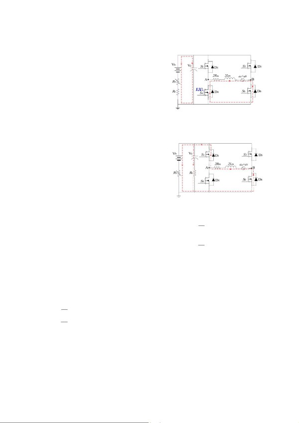
In a switching cycle T
s
, while S4 is turned on and others are
off, the armature inductance absorbs the released energy from
the back-EMF to pump up the terminal voltage of the armature.
The equivalent circuit of each commutation state is shown in
Fig.2, where the current i
L
flows through S4 and the
freewheeling diode D6. There are mainly two kinds of the EV
battery modeling approach. One is the electrochemical models
as in [25], which are widely used for battery design
optimization, heath characterization and control. The other is
the equivalent circuit models [26], which are primarily used for
online state-of-charge estimation and energy storage systems.
In this paper, a simplified equivalent circuit model is adopted as
in [2], which consists of a constant voltage source in series with
a variable resistance.
According to the principle of the KVL laws, the state
equations of the circuit in Fig. 2 are described as
S2_ON:
L
mmsdLab
11
c
cb
11
obccb
2(2 )
di
LRRRie
dt
dv
CRvRv
dt
VRRvRRv
−−
−−
⎧
=− + + +
⎪
⎪
⎪
=− +
⎨
⎪
⎪
=+
⎪
⎩
(2)
where d is the duty cycle, R
m
is the armature resistance, R
s
and
R
d
are the conduction resistances of the power switch and the
freewheeling diode, respectively; C and R
c
are the capacitance
and parasitic resistance of the dc-link capacitor, R
b
is the
equivalent load resistance of the battery, R= R
c
+R
b
; v
c
is the
voltage drop along the capacitor, v
b
is the battery voltage, V
o
is
the output charging voltage, and i
b
denotes the charging current.
−
−
+
c
i
b
i
+
L
i
Fig. 2. Equivalent circuit topology during S4 on (The red dotted line indexes
the current path.)
While the terminal voltage of the armature is high enough to
that of the battery, all the switches are turned off and the circuit
is equivalent to act as a non-isolated boost converter to charge
the battery as shown in Fig. 3.
−
−
+
c
i
b
i
+
L
i
Fig. 3. Equivalent circuit topology during S4 off (The red dotted line
indexes the current path)
Similarly, according to the principle of the KVL laws, the
state equations in Fig. 3 are described as
S2_ OFF:
1
L
mmdcbL
11
bccbab
11 1
c
bL c b
111
obcLbccb
2(22 )
di
LRRRRRi
dt
RR v RR v e
dv
C RRi Rv Rv
dt
V RRR i RR v RR v
−
−−
−− −
−−−
⎧
=++
⎪
⎪
++−
⎪
⎨
⎪
=−+
⎪
⎪
=++
⎩
(3)
2) Dynamic equivalent model of the charging converter
By selecting the state variables as x=[i
L
, v
c
]
T
and the output
as the charging voltage y=V
o
(t), the dynamic equations can be
transformed into the followings:
,
,
ON ON ab ON ON ON
OFF OFF ab OFF OFF OFF
ABegyC f
ABegyC f
=+ + =+
⎧
⎨
=+ + =+
⎩
xx x
xx x
(4)
where the coefficient matrices under S2_ON and S2_OFF are
1
2
0
0
ON
a
A
a
⎡
⎤
=
⎢
⎥
⎣
⎦
,
34
b
22
OFF
aa
A
Ra a
⎡
⎤
=
⎢
⎥
−
⎣
⎦
,
1
m
(2L )
0
ON OFF
BB
−
⎡
⎤
==
⎢
⎥
⎣
⎦
,
T
1
[0 ]
ON
g
g=
,
T
21b
[]
OFF
g
ggv=
,
1
b
[0 ]
ON
CRR
−
=
,
-1 -1
bc bOFF
CRRRRR
⎡
⎤
=
⎣
⎦
,
1
cbON OFF
f
fRRv
−
==
;
and the coefficients
1msdm
=(2 ++)/2aRRRL−
,
2
=1/aCR
−
,
3mdmcbm
=( +)/ /(2 )aRRLRRLR−−
,
4b m
=/(2 )aR LR
,
12b
=
g
av
−
,
2cmb
=/(2)
g
RLRv−
.
By multiplying both sides of the above equations by terms d
and d’=1-d, respectively, after average processing in state
网址:电动汽车中基于T https://www.yuejiaxmz.com/news/view/941313
相关内容
基于遗传算法的电动汽车有序充放电优化问题(附matlab源码)基于数据驱动的电动汽车实时充电研究
浅谈基于峰谷电价的电动汽车有序充电策略
【电动车优化调度】基于模型预测控制(MPC)的凸优化算法的电动车优化调度附Matlab代码
【电车】基于 V2G 技术的电动汽车实时调度策略附Matlab代码
【充电站设计】电动汽车充电站设计规范 电动汽车充电站通用要求
电动汽车冬季行车难,有何省电技巧
十大热门纯电动汽车 电动汽车排名 最好的新能源纯电动车
电动汽车整车能耗影响因素分析
深度解读!电动汽车充电站设备安全防范要点
随便看看
最新动态分享
- 分馆动态|“碳”生活易,叹生活难?海珠区图书馆南附分馆用这套模式给出了答案
- 北京搬家必看科普:别把值钱旧货当垃圾丢!老酒、红木、钱币上门回收攻略
- 奢侈品媒体|拉夫劳伦男装封神之作|奢华奢侈媒体
- 家里的废旧物品不要乱扔,几乎什么都可以用到手工制作上
- 旧物巧变身 亲子共护绿一一信阳市光山县特教学校开展创意手工艺品创作评比活动
- 北京家庭处理闲置:选对机构,真的省心又放心
- 片上总线学习之Wishbone
- 国交院举办毕业季跳蚤市场暨国际文化节活动
- 足不出户旧物回收 废物利用
- papi酱说陈龙像拾荒者 陈龙要断舍离 接地气生活获赞
热点动态分享
- 143857
- 44693
- 44045
- 39629
- 37373
- 29091
- 24256
- 24101
- 20449
- 17617